Static NAT with Service-Specific Mapping
August 12, 2025 - Reading time: 3 minutes
In the previous lesson, we learned how to configure basic Static NAT to permanently map an internal address to a public IP so that external users can access it. That configuration allowed all ports to pass through to the inside host.
In this lesson, we take that concept further by applying port-specific static NAT so that only a single service — in this case, HTTP on TCP port 80 — is reachable from the internet. This provides more control over what is exposed while still giving outside users access to the intended service.
eBGP Across Autonomous Systems
July 29, 2025 - Reading time: 3 minutes
Previously, we set up a simple two-router lab using both iBGP and eBGP, and we also demonstrated how to verify them. Now, we'll explore how eBGP and iBGP work together to exchange routes between different Autonomous Systems (ASes), highlighting their combined role in interconnecting more complex networks.
Topology Overview
This three-router topology connects three ASes:
- Router0 (AS 5110) connects to Router1 (AS 2640) using eBGP.
- Router1 (AS 2640) connects to Router2 (AS 2640) using iBGP.
- Only two static routes are used for initial reachability.
Open Shortest Path First
June 17, 2025 - Reading time: 3 minutes
OSPF (Open Shortest Path First) is a dynamic, link-state interior gateway protocol used within an autonomous system to exchange routing information between routers. It uses cost as its metric, calculated based on interface bandwidth, and ensures loop-free, efficient routing through the Dijkstra Shortest Path First (SPF) algorithm. OSPF organizes routers into areas to optimize scalability and convergence. Routers exchange topology information via LSAs (Link-State Advertisements), allowing each router to build a synchronized link-state database and independently compute the shortest path tree.
Each router is identified by a unique Router ID (RID), which must remain consistent in the OSPF domain. OSPF establishes neighbor relationships through Hello packets and forms adjacencies to exchange routing data. For any two routers to become neighbors, key parameters like area ID, hello/dead intervals, subnet, and authentication (if used) must match. All routers in a single area maintain identical link-state databases, ensuring consistent path selection.
GRE (Generic Routing Encapsulation)
June 3, 2025 - Reading time: 2 minutes
GRE (Generic Routing Encapsulation) is a tunneling protocol that allows the encapsulation of a wide variety of Layer 3 protocols inside IP tunnels. This enables the creation of logical point-to-point links between routers across an IP network. GRE tunnels are used to connect remote networks or routers that do not have a direct Layer 3 path, creating a virtual interface for routing. GRE itself does not provide encryption or authentication—its purpose is purely encapsulation and tunneling.
CallManager Express (CME)
May 20, 2025 - Reading time: 5 minutes
This lesson introduces you to Cisco CallManager Express (CME), a call-processing solution built into Cisco routers that allows you to register and manage IP phones without a separate server. You’ll configure the router to serve as both the telephony server and a DHCP server, which provides automatic IP addressing and TFTP configuration to phones. In this setup, each phone is registered manually using its MAC address, while DHCP assigns IP settings automatically. This is a common configuration in production environments where static control over phone registration is preferred, but dynamic IP management is still desired.
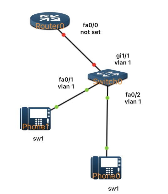
By the end of the lab, two Cisco IP phones will be fully registered to the router, receive their IP configuration via DHCP, and be able to call each other using assigned internal extension numbers.
eBGP Introduction
May 6, 2025 - Reading time: 5 minutes
In our previous lesson, we focused on iBGP—how routers within a single Autonomous System (AS) exchange routes internally. Now, we’ll turn our attention outward. External BGP (eBGP) handles routing between different ASes and is the backbone of how the Internet connects networks worldwide. Although eBGP uses many of the same commands and principles as iBGP, its peering relationships and behavior differ because each router typically belongs to a separate AS. In this lesson, we’ll step through a simple two-router eBGP lab, illustrate how to configure each side, and verify that both routers successfully advertise and learn each other’s routes.
What is eBGP?
- eBGP stands for External Border Gateway Protocol.
- It is used to exchange routes between different Autonomous Systems (e.g., between an enterprise network and its Internet Service Provider, or between two different ISPs).
- Each eBGP peer is typically a router under a distinct AS number, and the default Time to Live (TTL) for eBGP sessions assumes the routers are directly connected (one hop away).